Tectonic planet surfaces
Last changed on
Recently, I have been been spending some time on earth-like planetary surfaces, although not as much as I would've liked. Heh. And even though some progress is documented here on the Babylonjs forums, I am now thinking of providing more details on the various steps, problems and improvements that I encountered (and am still encountering) while dealing with this very interesting topic and its implementation.
The ultimate goal
Put very simply, AdLumens needs something that can apply the following rule for any tectonic planet:
for any point on a sphere, determine its elevation, its vertex colour, various physical characteristics such as pressure, etc. and data related to resources that can be found there: amount/concentration, extraction difficulty, etc. All in 16ms or less.
Now, at first glance this sounds simple and straightforward. I confess I even hoped at the beginning of the coding story of it all that I would come up with a magical "one formula to rule them all", a beautiful linear function that would simply run once and voilà! A few weeks later and I was wrong -- obviously; and things turned out to be far less… err … linear.
The original idea was not and is not a tantrum, though: it was for me the best way to implement code in rust that would be used both server- and client-side. More on this below if you are interested.
The spherical split
So how to implement the above? Well, with the childish "one formula" idiocy out of the way, the project is very roughly articulated around a split into two separate layers:
- A purely mathematical "virtual layer": this simply exists and lies inactive until it is queried for points data; this layer can be used server-side and client-side (on a need basis)
- A spherical representation of a planet surface is created and its points are used as "query values" to the virtual sphere; most of the time this will be limited to client-side operations
The virtual sphere
Is defined using various attributes, either physical or more "abstract". Some of these attributes are then used to initialise properties for the sphere, which will remain stable and unchangeable during its whole lifetime.
- Obvious stuff: identifier used as a base for seeding, radius, number of tectonic plates, etc.
- Several noise fields spread more or less evenly across the sphere surface, with configurables octaves, frequencies, etc.
The "physical" sphere
The first truth about the physical sphere is that it can be the outcome of any sphere approximation:
- Poisson
- Quadsphere
- Icosphere
- … or any other that I'm probably not aware of
This is true because whatever the chosen approximation model, the truth lies in the virtual sphere.
In the case of AdLumens, the icosphere was selected; the reason for this is mainly its slightly easier handling of distortion at the poles and its easy split management (at least for a conceptual perspective: it is extremely easy to visualise the split mechanism in one's mind and believe me… that helped me a lot!).
Whichever the representation type is selected though, the resulting mesh is just a simplified rendering proxy. Its discreetness is vastly different from the continuous nature of the virtual sphere. The points that result from the mesh construction are used as any other point would be used to query the virtual sphere.
Put another way: the physical sphere is a simplified and visual representation of the virtual sphere, tesselated to a certain resolution (based on performance requirements, etc).
Virtual sphere attributes
As of writing this, the virtual sphere can generate the following data (attributes, properties) for any given point.
| Attribute | Brief explanation | Physical sphere manifestation |
|---|---|---|
| Plate assignment | Uses a series of noise fields to assign a plate to the point. This is a good opportunity to say that plates are randomly generated using various attributes such as origin, surface_fraction, weight, etc. This is the starting point from which all other point attributes will be determined. None of the code is scientifically correct; hell, I even have smaller plates sitting in the middle of larger ones - the goal was to have and end result that looked ok. | 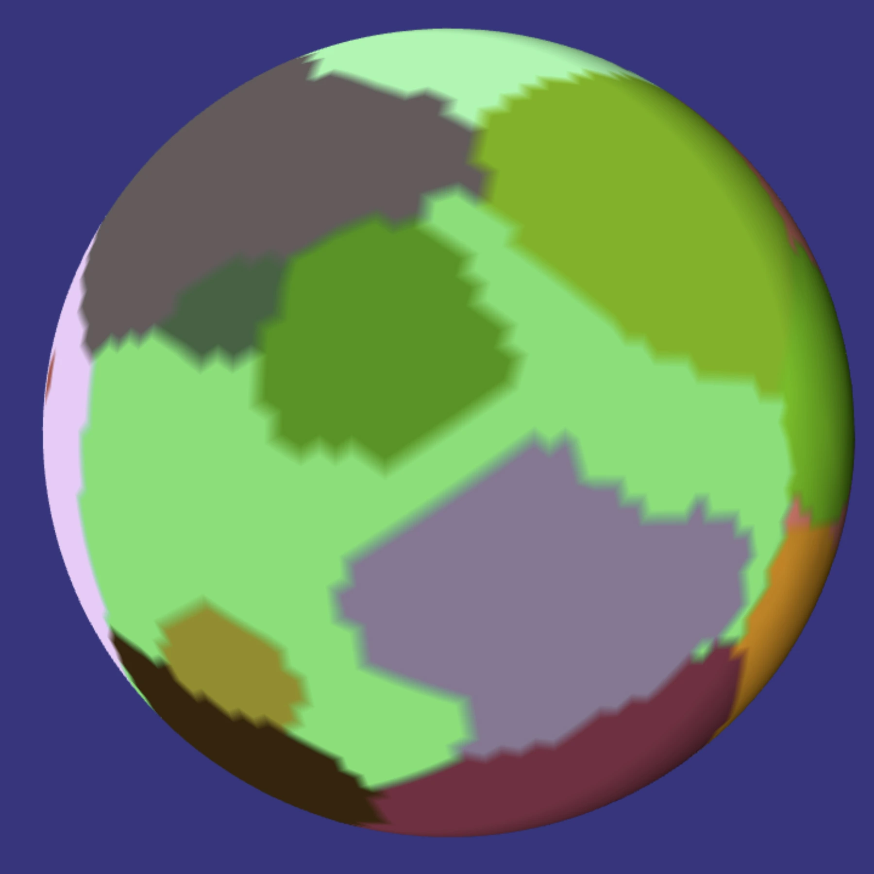 |
| Base elevation | This is directly derived from the assigned plate. At the moment, this is fairly "static" but is due to be influenced by various server-side parameters such as compound/mineral composition, overall crust level of activity, etc. | 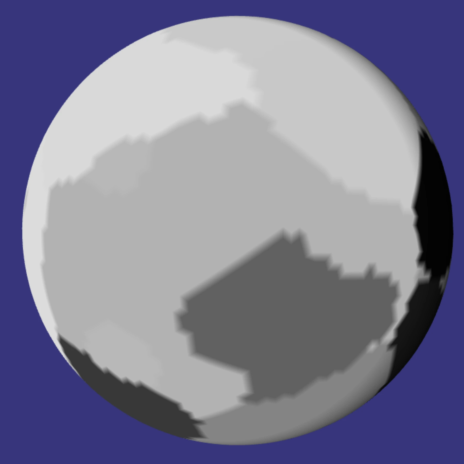 |
| Direction | Also derived from the assigned plate and its geodesic movement along the sphere, expressed as Vector2<f64> for [lon/lat]. The direction angle is slightly randomised on top of the one inherited from the plate. The end result is a direction field spread over the sphere, with potential strong variance across different plates, and weak ones within plates. | 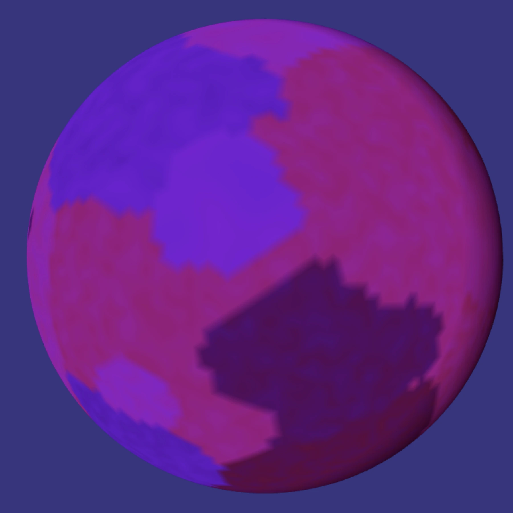 |
| Speed | Also derived from the assigned plate. Works in a similar fashion as Direction above. | 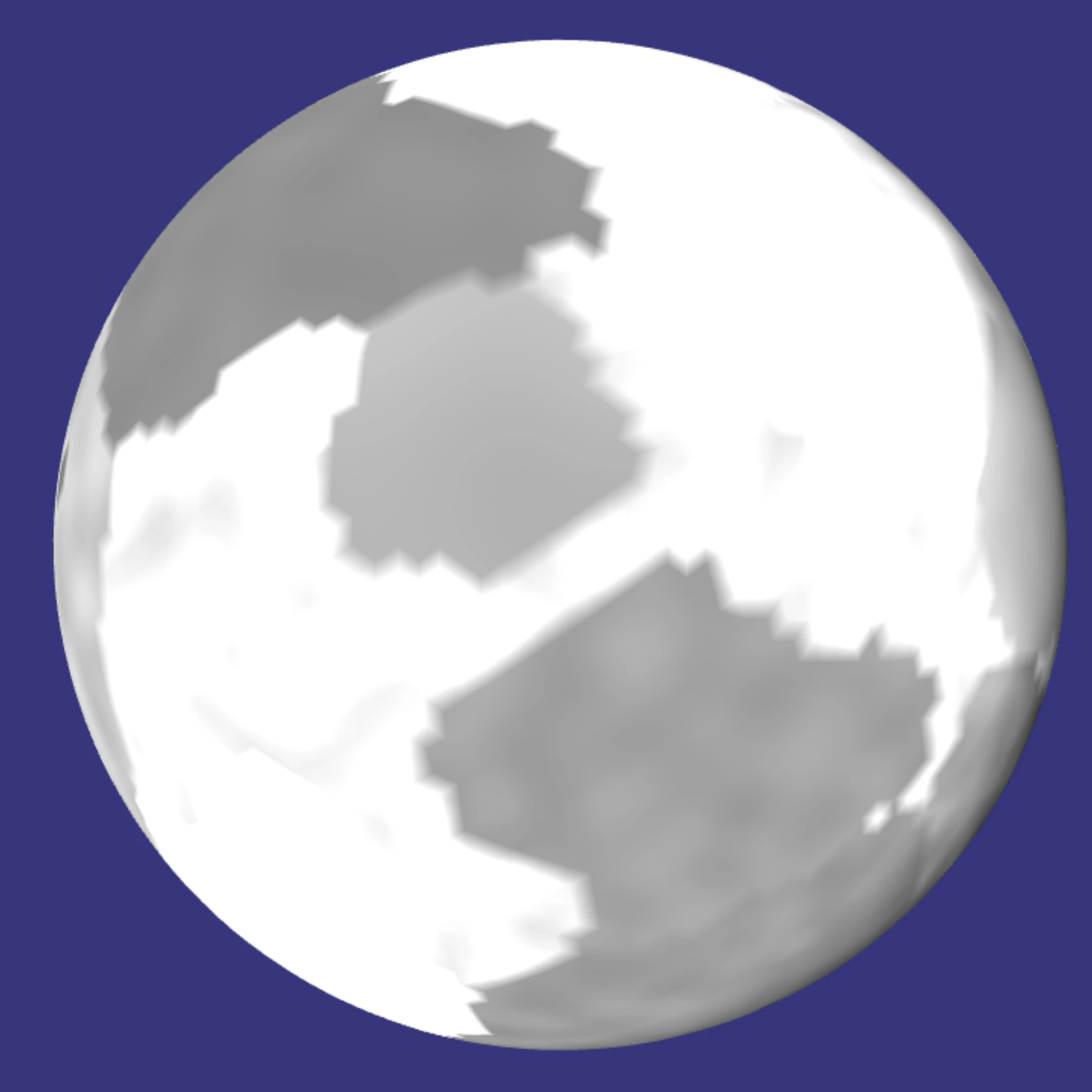 |
| Compression | Now entering the realm of more interesting stuff. This is computed by comparing direction, speed, boundary score and up/subduction effects (if any). The result is a f64 expressing the compression exerted at the point. It's all very abstract, so the number is dimensionless and can be negative. No Pascal or such units here. | 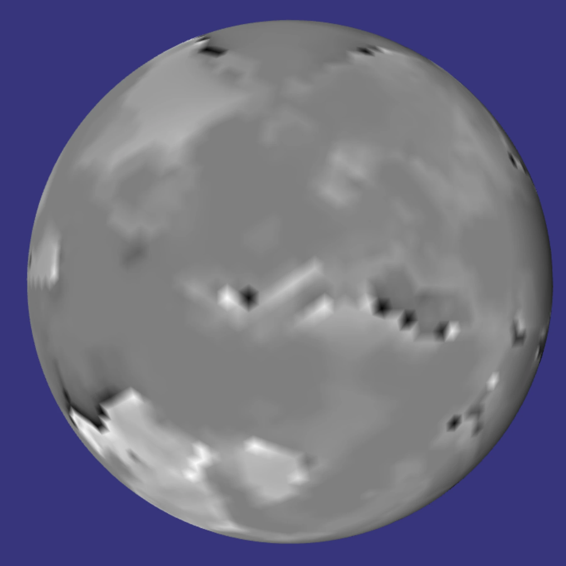 |
| Elevation | This is the first "visible outcome" and is how displaced vertices are going to be compared to their approximated base sphere position. Each point value can of course be negative or positive. | 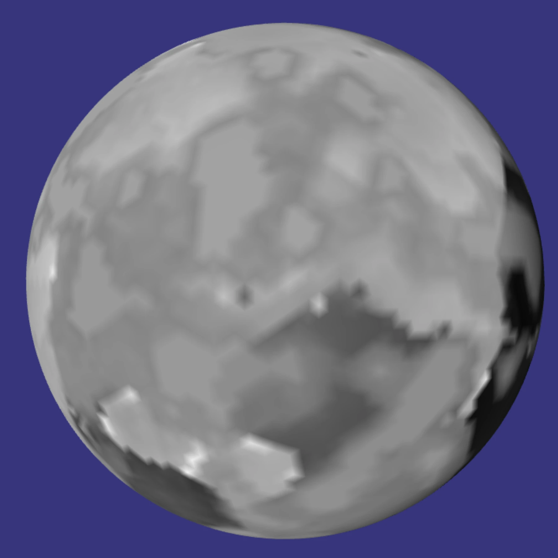 |
| Other fields | Fields for resources discovery and extraction. Will very likely be represented as dynamic heatmaps, with peaks depending on matching mineral types (igneous, metamorphic, sedimentary) versus boundary scores versus volcanic-crust activity. Although far from finished, this can lead to very interesting visualisation modes, such as the result of an ingame scan of a planetary surface, looking for compound X or mineral Y. Depending on the roll outcome, the resulting heatmap could be more or less accurate, be wrong (for critical failures, etc), and could be visualised by assigning the relevant colours to the mesh vertices. Food for thought… | - |
| Textures / actual colours | Well this one is complex. I think. I have several ideas on the subject, but none of them worth mentioning because again -- I need to start implementing them against performance constraints. | - |
As one can see, there is nothing scienfitic in there. Just what I hope is basic (if not intuitive) common sense, whose primary goal is to result in landscapes that look reasonably nice and realistic. Ho and that follows the "begin with the end" approach. The main reason is of course the time budget of 16 milliseconds, even when working inside a worker. A bit more on this below.
The images above illustrate visual outcomes at a low subdivision level (5), and the code behind them is being constantly modified. So take them with a grain of salt! :-)
Last, some new fields are very likely to become born, such as shear or rotation. They are in draft mode at the moment and their impact evaluated in terms of what they bring versus what they cost.
A brief history of versions
Full JS prototype
The very first quick & dirty prototype was this BabylonJS playground. By quick and dirty is meant: 1) it is slow 2) it is ugly 3) the randomness is really bad. But at least it got me into understanding what " basic steps" were going to be required for something hopefully more serious.
First rust/wasm version
The next step was to port the JS code to Rust, to be compiled as wasm. I initially tried wasm-bindgen but I thought that the generated Javascript was not that great, so I decided to do my own. The end result is something that takes up 10 times less space and -to me at least- is far easier to understand and maintain.
For example, being able to log messages from within rust/wasm to the Javascript console:
Javascript:
const load_wasm = async function(url) {
    let instance;
    const import_object = {
        env: {
            console_log: function(severity, ptr, len) {
                if(!instance || !instance.exports){
                    return;
                }
                const m = new Uint8Array(instance.exports.memory.buffer, ptr, len);
                const message = new TextDecoder('utf-8').decode(m);
                if(severity == 3){
                    console.error(message);
                }
                else if(severity == 2){
                    console.warn(message);
                }
                else{
                    console.log(message);
                }
            }
        }
    };
    await WebAssembly.instantiateStreaming(fetch(url), import_object).then(function(obj){
        instance = obj.instance;
    });
    return instance.exports;
};
Rust:
#[cfg(feature = "client")]
#[link(wasm_import_module = "env")]
extern "C" {
    fn console_log(severity:u8, ptr: *const u8, len: usize);
}

#[cfg(feature = "client")]
pub fn log_message(
    severity: u8,
    message: &str,
) {
    let bytes = message.as_bytes();
    unsafe {
        console_log(severity, bytes.as_ptr(), bytes.len());
    }
}

// usage
// equivalent to console.warn(`Hello from WASM: ${some_variable}`);
log_message(2, format!("Hello from WASM: {:?}", some_variable).as_str());
Rust feature
For a while I continued working on an isolated version of the rust code; meaning: the files were completely isolated from the main rust code base, as I did not want to potentially break the server-side builds.
Soon though, I had to tackle the ability of the server to make use of that code. Again, based on the authoritative server model, whatever the client can do, the server can -- and more. In the current context this meant that the server, just as well as the client, should be able to determine the exact characteristics of a point at the surface of a sphere; "why" does not matter - it must be able to do it as the client is the enemy. :-)
Initially I thought about writing a python script that would switch lib.rs files around. But then, and even though it meant a heavy rewrite of the rust code base, I opted for a more standard way of doing this: rust's feature err… feature?
Compilation is still invoked via a python script (hell, it's even a django management command!), with the following arguments:
| Argument | Explanation | Example |
|---|---|---|
os | Selects the targeted operating system: at the moment it's just win or linux. There are slight differences to how subprocess.run accepts parameters depending on where this whole thing is compiled from. Not a big deal, but enough to introduce that difference in the arguments. | On linux: |
feature | Selects whether we want to output:
| collecstatic |
WASM versus JS performance
Let's face it. JS engines such as V8 are monsters of optimisation, worked on by f**ing geniuses. I mean it. So I initially had serious doubts about wasm's ability to go fastah on loops, vector maths, and the like.
Initially… and even though wasm was about twice faster, I frankly was underwhelmed by the ratio this meant.
But then two things happened that completely changed this (apart from manual code optimisations, of course):
The first was enriching config.toml with the following:
[target.wasm32-unknown-unknown]
rustflags = ["-C", "target-feature=+simd128"]
… which is fairly safe to use nowadays unless you target Internet Explorer 10. :-P
The second happened by chance and it's a little bit funny. You see, the JS/WASM interface is all Float32Array. The "C/nomangle" rust functions all take f32s as input. So I had naturally assumed that, internally, f32s should continue to be used.
That changed when I had to integrate the previously isolated client-side code into the main rust code base, and had to migrate the internal floats to f64s. Ignoring the obvious precision gains, the performance impact was MASSIVE. Around 200% performance increase. I am not sure why, but I suspect that 1) rust more aggresively optimises/vectorises 64-bit operations 2) wasm, when using f64s, is closer to the metal on 64-bit CPUs? I frankly do not know, but the effect was quite positive! :-)
Internals
This section gives a brief overview of the internal processing that results in a mesh's visual outcome. It's fairly simple.
| Step | Performance cost | Some explanation |
|---|---|---|
| Initialisation | Negligible | A run-once per instance, this does several quick things:
Vec<f32> or Vec<u32>, where the data exposed to JS is crammed each tick: vertex_positions, vertex_indices, vertex_uvs and vertex_colors |
| Camera values | Negligible | Each tick, the Javascript tells the WASM "Hey these are my camera coordinates". It is not as simple as it seems as the camera data is made up of:
|
| Triangles processing | Medium | This is an important step that considerably helps reduce the load as it is essentially as dynamic LOD engine (a full icosphere at subdivision level 16 would be too heavy). It is not perfect at the moment, but works well enough. But the principle is simple: based on distance from camera, frustum intersection and backfacing ratio, decide whether a triangle should be split or merged. For each triangle:
|
| Triangle merging/splitting | Low | This step is the child of the previous one and involves several sub-steps:
|
| Vertex creation | Medium | Another very important step, touched on above with the pretty pictures. A few more details:
|
| Vertex data gathering | Negligible | The final stage, where the internal f64cough data is converted into f32 for Javascript. |
I must mention that the data structures used throughout the code are built around two main principles: O(1) for individual access and contiguous memory for loops. Hence, FXHashMaps and Arenas are used.
A couple videos…
Both in black & white: the colour gradient at each pixel is assigned from elevation.
This one is from a little while back:
This one is more recent:
As you can see, each "tick" takes about a few milliseconds, on a reasonable CPU (i9 12900HK)
In closing: next steps
Naturally, a new tools and experiments page will be added at some stage.
Then comes the question of how to integrate this little thing into the 3D explorer. Should it run inside the rendering worker? Or be invoked as another worker or set or workers from that rendering worker? The idea of splitting the work across several workers is seductive and would allow for LODs to be chunked and so for the overall visual quality to increase.
Food for thought again…
And last but not least, ground textures and atmosphere. Which as mentioned aboveI have started to investigate, but haven't gotten very far yet.
Well that was fairly long post. Hum.
Please signin to add your comment.